Aer-Max Installation Instructions
Congratulations on selecting this quality Aer-Max system.
Important: Please read all instructions before assembling and installing the Aer-Max system. Consult local plumbing & electrical codes. Identify all parts before assembling.
- Section 1 : Assembly & Installation of the Air Pump
- Section 2 : Setting & Checking Head Pressure
- Section 3 : Installation of Vent Tank & Head
- Section 4 : Installation of Double Aeration
- Section 5 : Electric Connection for Air Pump & Maxivent
- Section 6 : Installation of Maxivent System
- Section 7 : Installation of the Air Pump & Maxivent with Well Pump Pressure Switch as power source
- Section 8 : Installation of the Filter Tank(s)
- Section 9 : Regulating Airflow — ARV Settings
- Section 10 : Ozone Applications
- Section 11 : Warranties
- Section 12 : Trouble Shooting Guide
- Appendix : Pure Water Products’ Aer-Max Aeration Tank Head Diagram
Section 1 : Assembly & Installation of the Air Pump
Parts List
The following parts are needed for pump installation:
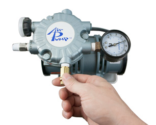
- (1) Air Pump w/ Air Filter
- (2) 1/4" Check Valve
- (1) Air Regulator Valve (ARV)
- (3) Rubber Feet or Shelf w/ (3) Vibration Mounts
- (1) Pressure Gauge
- (2) Tubing Connectors
- (1) Poly Tubing
Caution: Do not over-tighten fitting. Pump head will crack!
-
Use Teflon tape on male thread connections.
-
Remove side plug and back plug on outlet side of pump head. Use a 1/4" Allen wrench or channel locks.
-
Install pressure gauge in back port (opposite outlet).
-
Install Air Regulator Valve (ARV) into side port.
-
Install first check valve into front outlet port. Arrow and flow should point away from Air Pump toward injection point. Reserve second check valve and tube connectors for installation explained in Section 7.
-
Air Pump assembly is complete. It can now be tested for head pressure.
-
Thread the three vibration isolators or rubber feet into base of pump when ready to mount and install. See Section 7

Section 2 : Setting & Checking Head Pressure
Note: Air Pump should be assembled before continuing.
Checking Head Pressure:
-
Loosen lock nut (counter-clockwise) on Air Regulator Valve (ARV).
-
Turn adjustment nut counter-clockwise. Back out at least half way. This will relieve the tension on the ball and spring allowing air to flow freely out the ARV. This will prevent excess pressure from building up when you close off outlet port. DO NOT LET PSI EXCEED 100 PSI.
-
Plug Air Pump into an appropriate voltage outlet.
-
Slowly close off outlet port — this will simulate line pressure. To close outlet use:
-
1/4" ball valve threaded on check valve. (Not included.)
-
1/4" cap threaded on check valve
-
Temporarily remove check valve and use extra plug.
-
For lower psi settings, hold thumb over check valve.
-
-
Continue to gradually seal off outlet port. Air should be free flowing from ARV and the pressure gauge reading should be zero. If not, continue to turn adjustment nut counter-clockwise to release pressure.
With Air Pump on, outlet port completely close, and pressure gauge reading at 0 psi, air should be flowing from ARV.
-
 Building head pressure.
You are now ready to test the ability of the Air Pump to build head pressure. You can also set ARV at a desired pressure (explained at the end of this section).
To build up head pressure, gradually rotate clockwise the adjustment nut on ARV. The pressure will begin to rise as you increase the tension on the ball and spring. Do not exceed 100 psi.
When the desired pressure is reached and air is releasing out the ARV, the Air Pump is set at the proper head pressure to introduce air into the water line pressure.
Do not set ARV above 75 pounds because this could cause the standard water pressure relief valve (usually located on pressure tank) to possibly dischage water in the event of excess pressure build up. When using the Maxi-Vent the recommended setting for the ARV is at the cut out pressure on the pressure switch.
Setting & Securing ARV Setting:
-
Use adjustment nut to set desired pressure, then thread lock nut clockwise and secure it against the ARV body. Snug lock nut with wrench. This will lock adjustment at the desired pressure setting.
-
If pressure does not build while turning in adjustment nut, check the 3 ports on the outlet side of Air Pump for leaks (Pressure gauge, ARV, and outlet port).
-
When pressure builds up to the desired pressure and ARV is secure, the Air Pump assembly is complete. (See Section 9 for Regulating Airflow of the ARV)
Section 3 : Installation of Vent Tank & Head
Parts List:
- (1) PVC Head w/ O-Rings
- (1) 1/2" CPVC Vent Distributor Tube
- (1) Inlet Diffuser
- (1) Riser Tube
Setting up the System
-
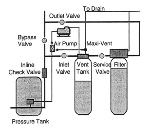
Please note diagram at right. An inline check valve is required, but not supplied with this equipment.
The check valve needs to be installed in a vertical position prior to the vent tank but after any untreated lines, if any. It is best to have a vertical column of water at least 12 inches on top of the check valve before the vent tank. The inline check valve prevents air from back flowing from the vent tank.
-
Position systems close to power source. Please note that the Air Pump should be installed above the injection point located on the PVC head or before 4" the inlet of the head.
-

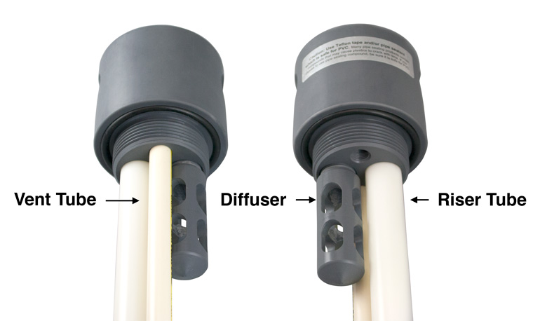
Glue 1/2" CPVC vent tube into the bottom 1/2" hole of the PVC Head. This is where the air will vent.
-
Thread inlet diffuser hand tight into bottom 3/4" hole of PVC Head and note “inlet” mark on the top of the Head.
-
Lube and install 1.05" riser tube in the Outlet and cut the length to 4" from the bottom of the tank.
Note: If using the double aeration option, please skip to Section 4
Section 4 : Installation of Double Aeration (Optional)
Note: If the double aeration kit was not ordered, skip to Section 5
Parts List:
- (1) PVC Head w/ O-Rings
- (1) 1/2" CPVC Vent Distributor Tube
- (1) Fishstone w/ 1/4" Fitting
- (1) 1/4" M-Thread x 3/8" Compression Fitting
- (1) Length of 3/8" O.D. Poly Tubing
- (1) Inlet Diffuser
- (1) Riser Tube
- (1) Nylon Tie
Note: Due to the size and shape of the fittings on the bottom of the head, assembly must be done in the exact order listed below.
-
Wrap the 1/4" male compression fitting with Teflon tape.
-
Thread fitting into bottom 1/4" hole of PVC Head. Line up the hex nut on the compression fitting to allow clearance for air diffuser. The fitting cannot protrude into the area of the 3/4" air inlet diffuser hole.
-
Connect one end of the compression fitting. Secure by hand tightening.
-
Lube and install 1.05" riser tube in the Outlet and cut the length to 4" from the bottom of the tank.
-
Extend poly tubing along riser tube and cut a 7" clearance from bottom of riser tube. Attach tubing to distributor tube with nylon ties.
-
Insert barbed fitting of fishstone into poly tubing.
-
Thread inlet diffuser (hand tight) into 3/4" hole in bottom of PVC Head.
Section 5 : Electrical Connection for Air Pump & Maxi Vent
Note: The electrical power source will normally be from the load side of the pressure switch. Be sure to match Air Pump and Maxi-Vent voltage to well pump voltage. It will be necessary to install a double receptacle for 115 volt or two single receptacles for 230volt applications. One receptacle is needed for the Air Pump and one for the Maxi-Vent ( See Section 6).
-
Electrical Connection: Install appropriate 115 volt or 230 volt receptacle and connect wire from receptacle to pump (load) side of pressure switch. This will allow the Air Pump and Maxi-Vent to turn on and off with the well pump.
Section 6 : Installation of Maxi-Vent System
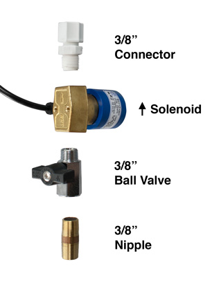
Parts List:
- (1) 3/8" Tube by 3/8" MIP Connector
- (1) 3/8" x 1-1/4" Brass Nipple
- (1) 3/8" Tube x 1/2" MIP Connector
- (1) 1/2" Barbed x 1/2" Female Thread Poly Tee
- (1) Solenoid
- (1) 3/8" Ball Valve
-
Assemble fittings according to diagram. Use Teflon tape or Teflon pipe dope for threaded fittings.
Note: The solenoid is marked with a directional arrow. Please install solenoid as shown.
-
Thread assembled Maxi-Vent into Vent Head.
-
Run poly tubing from 3/8" male connector at top of Maxi-Vent and tee into the drain line of filter tank(s) or to any other acceptable discharge point.
-
Connect poly tubing to the drain line using the 3/8" tube x 1/2" male connector and the 1/2" barbed x 1/2" female thread tee.
-
Plug power cord into outlet where the Air Pump is connected.
Note: Secure poly tubing and filter drain line to prevent dislodging during discharge of air and water. Be sure to install appropriate air gap.
Important: Do not plug Maxi-Vent into constant hot electrical source.
The Maxi-Vent will release water and any excess air/gas while the Air Pump is introducing air. Once the air reaches the base of the vent distributor tube in the vent tank, the air pocket is full. Air will begin to enter the vent distributor tube and exit the Maxi-Vent to drain. This will continue until the Air Pump and Maxi-Vent are deactivated.
Using the Ball Valve on the Maxi-Vent
The brass ball valve will be used as a shut-off for cleaning and servicing. It is also used to regulate the flow of air and water. Recommended flow regulation is usually between 0.5gpm and 2.0 gpm.
Using a Flow Switch with the Maxi-Vent
When using a flow switch to activate the Air Pump and Maxi-Vent, install after the vent tank and Maxi-Vent. If the flow switch is installed before the Maxi-vent, there will be a constant stream of water to the drain as the demand for water keeps the flow switch and Air Pump activated.
Section 7 : Installation of the Air Pump and Maxi-Vent with Well Pump Pressure Switch as the Power Source
-
Position close to electical source and injection point. Installer may choose to:
-
Secure Air Pump with feet.
-
Mount on a shelf.
-
Suspend with straps.
-
-
Install second 1/4" check valve into Vent Head. Be sure the arrow and flow are pointing into injection point and away from Air Pump.
-
Install a tubing connector on each check valve (located on vent head and Air Pump).
-
Connect tubing from Air Pump to injection point.
-
Tighten all fittings making sure not to over-tighten.
-
Turn water on. Check for leaks.
-
Plug Air Pump and Maxi-Vent into receptacle. Run well pump through a few cycles during the backwash and rinse cycles ( See Section 8 ).
-
Fine tune or adjust Air Pump as need. (See Section 9 ). Increasing the size of the holes in plastice cover can eliminate excessive noise from the air filter. (Please remove cover before drillin existing holes larger.)
Note: Pump should be installed above the injection point. Compressed air will create condensate. Mounting above the injection point allows condensate to flow down toward injection point. This will help reduce moisture build-up from back flowing into Air Pump.
Section 8 : Installation of the Filter Tank
-
Insert distributor tube into the tank. Locate center of distributor on bottom of tank. Top of the tub should be flush with tank top.
-
Place wide mouth funnel on to tank. Add gravel under-bedding to tank, covering distributor barrel.
-
Pour media into tank. Approximate media levels:
-
Calcite = 2/3 full, allow 1/3 of tank for backwash expansion.
-
Carbon & Birm = 1/2 full, 1/2 of tank for backwash expansion.
-
-
Clean tank, lip and top of distributor of dust and debris.
-
Apply silicone lube to top one inch of distributor tube, to o-rings on control base and in the distibutor pilot.
-
Install control to tank. Thread into tank hand-tight only.
-
Connect piping to drain line.
-
With water supply off, place the bypass valve(s) into the service position. Advance control into backwash cycle.
-
Open water supply valve very slowly to approximately the 1/4" position. In this position, you should hear air escaping slowly from the drain line.
Caution: If opened too rapidly or too far, mineral may be lost. -
When all of the air has been purged from the tank (water begins to flow steadily from the drain), open the main supply valve slowly. Increase flow to remove fines from media but use caution to prevent from blowing media out to drain.
-
Allow water to run to drain until clear.
-
Advance to rinse cycle and run water until clear.
-
Set the time of day and the frequency of backwash.
-
Check for leaks and turn system on.
-
Run water downstream from the system for several well pump cycles. Be sure you hear water splashing in the vent tank. If no splashing, check Trouble Shooting Guide.
-
Adjust Maxi-Vent (see Section 6).
-
Regulate airflow on Air Regulator Valve (see Section 9).
Caution: Do not allow media to enter distributor tube.
Repeat step 11-13 to clear fines. Gently tapping sides of tank will help clear fines. Tap tank with rubber mallet while in backwash cycle. Monitor drain line to be sure mineral is not being backwashed out.
Section 9 : Regulating Airflow - ARVS Settings
Note: When using Maxi-Vent with the Aer-Max System, higher ARV settings can be used. The Maxi-Vent expels air at a faster rate then a mechanical vent.
To adjust the Air Regulator Valve (ARV), loosen lock nut (thin nut in the middle of fitting). Now the outer adjustment nut can be turned clockwise to increase pressure and airflow; or counter-clockwise to reduce pressure and air flow during well pump cycle. If threaded out too far, air will flow freely out of regulator valve instead of pumping air into water line. Furthermore, if adjustment nut is removed, the check-ball and spring will fall out. If this happens, simply insert ball and spring and thread nut back in.
While the well pump and Air Pump are running you can set the Air Regulator Valve to desired pressure. Start with ARV halfway open. As you turn adjustment nut clockwise, pressure will build in pump head. When pressure at head meets line pressure, air will be pushed into water line. When using the Maxi-Vent the recommended setting for the ARV is at the cut out pressure of the pressure switch.
To descrease or limit the introduction of air, set the ARV 5-10 pounds above the start up pressure of well pump. When the well pump starts up, the Air Pump also turns on, adding air during the beginning of pump cycle. Once the line pressure exceeds the setting on Air Pump ARV, no more air will be introduced into water line. The Air Pump will continue to run during the rest of the pump cycle but the excess air will be released out the ARV. (You should be able to hear or feel the air escaping.) If more air is desired, gradually set ARV to a higher pressure.
| Examples | Air Input | Well Pump Setting | ARV Setting |
|---|---|---|
| Minimum | 30 - 50 psi | 35 psi |
| Medium | 30 - 50 psi | 40 psi |
| Maximum * | 30 - 50 psi | 50 psi |
* Maxi-Vent may allow for maximum ARV setting due to the high rate of air discharge.
After setting ARV adjustment nut, secure lock nut to regulator body by rotating clockwise. This will lock the setting of the ARV. To re-adjust, loosen lock nut, reset adjustment nut, and secure lock nut. Follow up visits may be required to fine tune ARV.
Section 10 : Ozone Applications
-
Consult Ozone manufacturer when using Air Pump for Ozone Applications.
-
Ozone voids the Air Pump Warranty.
Section 11 : Warranties
We design Aer-Max Systems based on accurate water analysis and flow rates. Because we are unable to verify this information and we are unable to determine proper installation of equipment, we assume no liability for the determination of the proper equipment necessary to meet your requirements, and we do not authorize others to assume such obligations for us.
Air Pump Water Solutions, Inc. warranties its Aer-Max System as follows:
-
Fleck Controls: 3 year limited warranty
-
Structural Fiber Tanks: 10 years against rust and corrosion
-
Maxi-Vent: 1 year unlimited against manufacturer defects
-
Air Pump: 1 year from the date of manufacture unlimited warranty for defective materials or workmanship in manufacturing. This warranty covers replacement parts for the AP1 and AP2, as well as the cost of the labor to replace them when, proven to our satisfaction, that these parts are defective. Users of ozone may receive full warranty on the Air Pump only when the compressor is “pushing” air into an ozone generator. The warranty is void when ozone is drawn through the Air Pump. This warranty is extended to the original purchaser at the original installation address when the pump is purchased from an authorized Air Pump Water Solutions, Inc. dealer.
Air Pump Water Solutions, Inc. assumes no responsibility for consequential damages, labor or expense as a result of any defect or failure due to circumstances beyond our control. Air Pump Water Solutions, Inc. will not be held liable for any fire damage, water damage, or damage to other water treatment equipment and plumbing due to malfunction of the Aer-Max System. Air Pump Water Solutions, Inc. has no control over misapplication or improper installation of the Aer-Max Systems, or improper installation of other water treatment devices.
The laws in your state may not allow limitation for responsibility for consequential damages, and this warranty may give you other legal rights that vary from state to state. Product improvements and design changes subject to change without notice.
Section 12 : Trouble Shooting Guide
After trying these possible solutions and your problem continues, you may call Air Pump Water Solutions toll free in USA and Canada at 1 877 4-AER-MAX (423 7629).
PROBLEM : Air spits and sputters from untreated lines. Possible cause is air is escaping from the aeration tank and is back flowing through the check valve, which may be installed in a horizontal position or has debris — preventing check from sealing.
SOLUTION : Install check valve in a vertical position so that there is a column of water standing about a foot or more before the vent tank. See Section 3, Step 1.
PROBLEM : No air bubbles in water and discoloration returns. The cause may be a water logged vent tank, a malfunctioning Air Pump, or no primary check valve. See above solution.
SOLUTION : Run water in house and listen for splashing in vent tank. See above solution. Plug Air Pump in alternate power source and observe pressure gauge on pump. Air Regulator Valve may have “drifted” to a lower pressure. See Section 2, Step 10, “Setting Head Pressure”, to the cut out pressure.
PROBLEM : Water problems were initially solved but returned a few days later. Possible solution is a restriction in the backwash system.
SOLUTION : Make sure there is no kink in backwash line. Also, advance filter control to backwash and measure water flow from drain. A 5 gallon bucket will fill in one minute if there is no restriction.
The flow may be restricted due to media lodged in the backwash chamber and/or backwash flow control button (washer). With water completely shut off, advance filter into backwash position. Use caution — unit may still be under pressure and may spray out water when drain line is removed. Remove locking pin where drain line is connected to filter. Remove fitting and clean out media. Re-connect and gradually open inlet valve to flush out excess mineral. Re-check flow rate from end of drain line.
PROBLEM : Low flow of water. This can be caused by a valve not being fully opened or, if the problem occurs a few weeks after initial installation, the filter media being fouled with iron or sulfer bacteria. Examine the media bed. It may need to be stirred and backwashed again to remove fines.
SOLUTION : If bacteria is present, it will be necessary to modify the equipment. A chlorinator or other modification will solve the problem.
PROBLEM : No odor but discoloration is present. This may be caused by the presence of tannins or colloidal iron, or an undersized filtering tank.
SOLUTION : Aeration does not solve tannin or colloidal iron problems. Most filter media require twice as much flow rate for backwashing as they do for filtering. Higher flow rates may require two filter tanks in parallel in order for proper filtration. Well flow rate is determined by counting the gallons drawn down and the time between cut in and cut off cycle of the well pump. The formula for determining the flow rate is to measure the number of gallons drawn down, divided by the seconds required for recovery. Then, multiply the result times 60 seconds.
PROBLEM : Air Pump does not build up pressure. This can be caused by check valves leaking water to the compressor, an Air Pump damaged during shipping or with a manufacturer's defect, or an error performed in installation.
SOLUTION : Unplug the outlet of the compressor and plug into an alternate power source and observe pressure gauge. If the presure does not come up to desired level, go to Section 1 and make certain that the fittings are installed in the exact ports shown in the diagram. Except for small droplets on the poly tubing, there should be no water present. Test the 1/4 inch check valves if water is present in the tubing. They may need replacement.
Be sure the Air Pump is mounted above the level of the injection point. A damaged or defective Air Pump is rare. Please explore solutions before calling for a return authorization number.
PROBLEM : Sulfur odor is reduced, but not eliminated. Possible cause is that there is not enough turnover of air.
SOLUTION : Generally, hydrogen sulfide requires more air turnover than iron. Be certain that the Air Regulator Valve on the Air Pump is set at the maximum cut out level of the well pump.
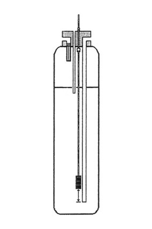
AerMax Aeration Tank Head
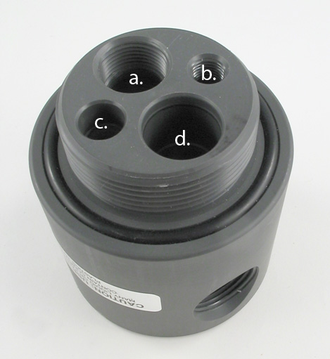
Getting Everything in Its Right Place
Your unit will need something in each of the four holes shown if it has double aeration. If it doesn't, hole “b” will be empty.
-
This is where the threaded plastic baffle is screwed in. This is the port where water to be treated enters.
-
This is where the double aeration tube is screwed in. It is the port where air enters the tank. It will be left unused if your unit does not have the double aeration feature.
-
The smaller unthreaded hole is where excess air is vented from the air tank. Push in the smaller diameter tube (the square-cut end goes into the hole).
-
This is the port where treated water leaves the tank. Note that it has an O-Ring. Push the larger tube as far as it will go into the port.
Site Index
Filtration Systems
- Aeration for Iron & Sulfide
- Backwashing Filters
(whole house & well units)
- Chlorine & Chemical Injectors
- Countertop Water Filters
- Garden Hose Filters
- Reverse Osmosis, Residential
- Reverse Osmosis, Commercial
- Shower Filters
- Specialty Filters
- Ultraviolet Systems
- Undersink Filters
- Water Softeners
- Whole House Filters
Cartridges
Parts
- Replacement Parts
- Faucets
- Filter Media
- Fittings
- Housings
- O-rings
- Pumps
- Pura UV
- R.O. Parts
- R.O. Tanks
- R.O. Booster Pump
- VIQUA UV